How I built my own WiFi modem for my old Atari ST
Introduction
In this post, I describe how I used a Raspberry Pi Zero W and an RS232-to-TTL adapter to build an inexpensive WiFi modem for my 33-year-old Atari 1040 ST computer. This WiFi modem also serves as a shell account server, much like the ones we dialed into to connect to the Internet in the late eighties and early nineties. Although I have only tested it on my Atari ST, it should also work with any computer that has a DB9 or DB25 RS232 serial port, like a Commodore Amiga or an old IBM compatible PC.
Components
In order to build the WiFi modem, you will need the following components:
-
A Raspberry Pi Zero W single board computer
Make sure you get the Zero W model and not the Zero model. The Zero W model comes with added WiFi support, that we will need. If you are like me and are not very comfortable with a soldering iron, you can opt for the Raspberry Pi Zero WH model. This one comes with a pre-soldered GPIO header and costs about $4 more.
-
A MicroSD card with a capacity of at least 8 GB
-
A Micro USB power supply
I recycled an old Micro USB cable and an old iPhone charger and saved a few dollars.
-
A Break-away 0.1” 2x20-pin Strip Dual Male Header
If you buy the Raspberry Pi Zero WH, with pre-soldered GPIO header, you don’t need to worry about this.
-
An RS232 to TTL Converter
I used the NulSom Inc. Ultra Compact RS232 to TTL Converter with Female DB9 (3.3V to 5V) and it worked well.
-
Male to Female DB9 to DB25 Serial Adapter
If your old computer has a 25-pin serial port, like my Atari ST, you will need an adapter to connect the RS232 to TTL Converter’s 9-pin female connector to the computer’s 25-pin male connector. I used this one.
-
We will break away a four-pin strip and solder it to the RS232 to TTL Converter.
-
Multicolor female to female jumper wires
We will use these to connect the RS232 to TTL Converter to the Pi Zero W’s GPIO header. We will only need four of these jumper wires.
-
A soldering iron
-
Solder
-
A modern computer with a MicroSD card port
We will use this computer to install the Raspberry Pi OS operating system on the MicroSD card.
Steps
-
Follow these instructions to install the Raspberry Pi OS operating system on your MicroSD card using the Raspberry Pi Imager.
There are different versions of Raspberry Pi OS that you can install. I installed Raspberry Pi OS Lite (32-bit) because I do not expect to use the desktop environment.
Do not install the MicroSD card on your Pi Zero W until you have completed the following three steps.
-
Remove the MicroSD card from your computer and reinstall it, so that it is recognized by your computer.
-
Follow these instructions to configure your Pi Zero W to connect to your wireless network.
The Pi Zero W does not support the 5 GHz band. You must use the 2.4 GHz band.
-
Enable SSH on your Pi Zero W by creating a new empty file named ssh, without any extension, in the root directory of the MicroSD card. This will allow you to connect securely to the Pi Zero W from another computer on your network.
-
Eject the MicroSD card from your computer.
-
Insert the MicroSD card into your Pi Zero W, plug the Micro USB cable from the power supply into the Micro USB port labeled PWR IN, and wait a few minutes for the computer to boot.
-
Connect to the Pi Zero W using SSH.
These are the instructions for MacOS or Linux and for Windows 10.
Raspberry Pi OS supports Multicast DNS out-of-the-box. The host name of the Pi Zero W on your network should be raspberrypi.local.
The default login is: pi The default password is: raspberry
-
Immediately after logging into the Pi Zero W, change the password of the pi user using the following command:
passwd
-
On the command line, type the following:
sudo nano /boot/config.txt
-
Use the cursor keys to go to the end of the document and add the following line:
enable_uart=1
-
Save the file by pressing Control-O and pressing enter.
-
Exit nano by pressing Control-X.
-
Disconnect the power to the Pi Zero W.
-
Solder the 2x20-pin Strip Dual Male Header on the top of the Pi Zero W.
This video from DroneBot Workshop shows how to solder the GPIO header on the Pi Zero W. Again, if you are not comfortable with the soldering iron, you can use a Pi Zero WH that comes with a pre-soldered GPIO header.
-
Break away a four-pin strip of breakaway headers and solder it on top of the VCC, TX, RX, and GND holes in the RS232 to TTL Converter. The TX hole is the one with an arrow pointing away from the converter and the RX hole is the one with the arrow pointing into the converter. Make sure the black chip is facing up.
-
Connect the jumper cables as follows:

-
If your old computer has a DB25 serial port, connect the Male to Female DB9 to DB25 Serial Adapter to the RS232 to TTL Converter and to the serial port on your old computer. Otherwise, just connect the RS232 to TTL Converter directly to the serial port on your old computer.
-
Plug in the power cable to the Pi Zero W.
-
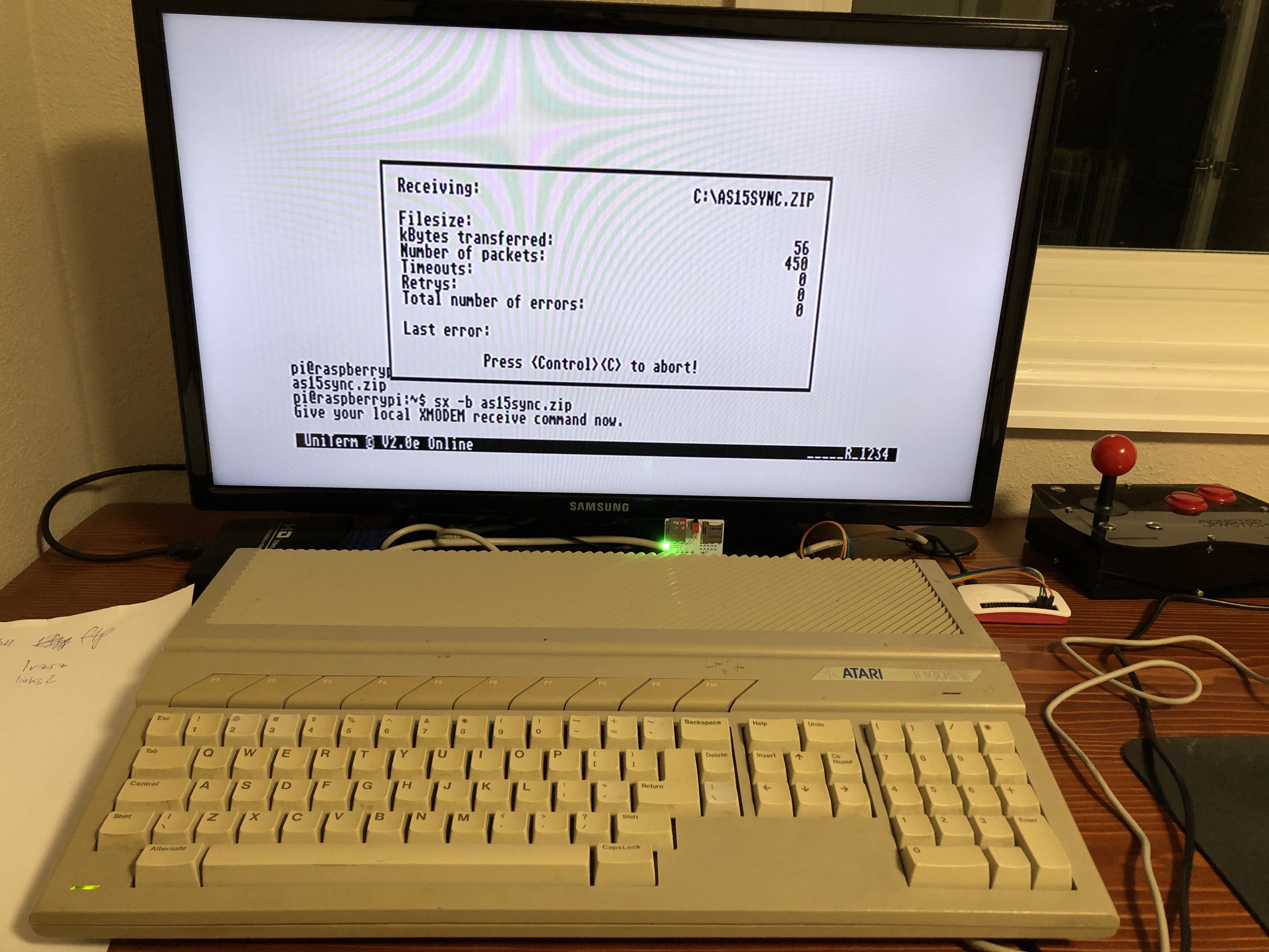
Turn on your old computer and open a terminal program. I use Uniterm on my Atari ST.
-
Set your terminal program to 9,600 baud [sic], XOn/XOff flow control, no parity, 8 data bits, one stop bit, and full mode.
-
Press enter a couple of times, and the Raspberry Pi OS login prompt will appear.
-
Enter your login (pi) and password to log in.
You are now connected to a shell account on the Raspberry Pi Zero W with access to the Internet.
Conclusion
In this post I showed you how to build an inexpensive WiFi modem for old computers using a Raspbery Pi Zero W and an RS232-to-TTL adapter. In my next post I will show you how to use your new WiFi modem and shell account server to download files from an FTP server to your computer using XMODEM.